The ELMB & ELMB-DAC
ELMB + LMB-DAC
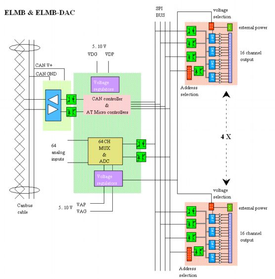
This is a block schematic overview of the ELMB with the ELMB-DAC connected to
it.
The ELMB is connected to the CAN bus via a CAN transceiver. This transceiver
translate the differential and bi-directional CAN signals into two
unidirectional TTL level signals. The transceiver is optically separated from
the CAN controller and its associated micro-controllers. So the
CAN-transceiver gets its own power-supply via the same cable as the CAN
signals. The micro-controller has it's one power namely Digital power plus and
ground. (VDG&VDP) The micro controller is connected with the outside world
with a SPI or Microlink bus. On the same ELMB is also an analogue part. A 64
channel multiplexer and a 16-bit ADC are connected via opto-couplers with the
SPI bus. This analogue part has its own power namely Analogue voltage plus and
ground. So, if you have to make very sensitive and accurate measurements then
you should use a separate analogue power-supply.
The ELMB-DAC
The ELMB DAC
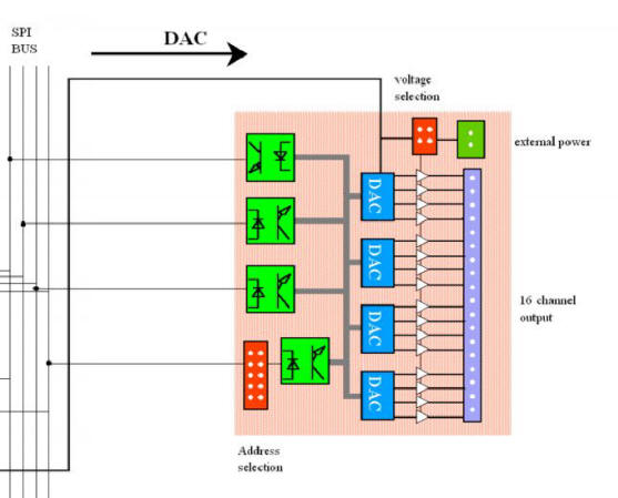
The DAC (MAX525) is connected via opto-couplers with the SPI bus. It has an on
board address selection that enables one to connect four DAC PCB's to one ELMB.
This number has been chosen because the DAC gets its power from the ELMB and
that power is limited. There are four DAC's on one PCB and each DAC has four
channels so each PCB has 16 channels. Each DAC channel has an output circuit
that can be supplied with the internal power-supply of the ELMB or can be
externally supplied with an external power supply. In case the DAC is
internally fed, the output current can be within 0 to 1 mA. In case of an
external power supply, the output current can be 0 to 20 mA.
 Output
circuit
Output
circuit
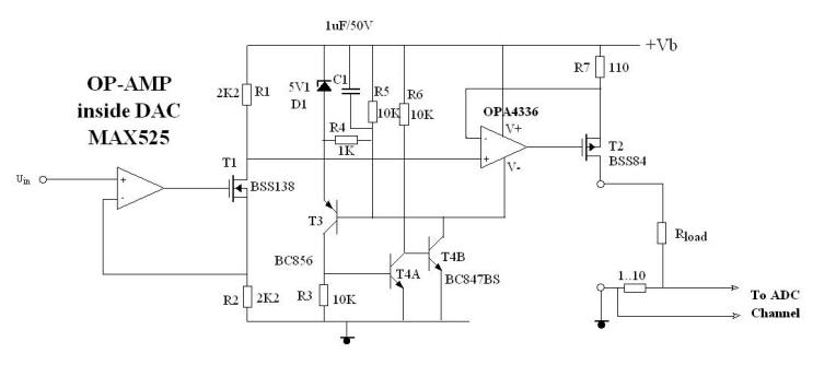
This is the output circuit of the LMB-DAC. An op-amp inside the MAX525 DAC is
used and one op-amp from Burr brown the OPA4336. Both the MAX525 and the
OPA4336 are not certified for use in a radiation area, so the have to be
tested. The maximum output current is 1 mA when R1 and R7 are 2.2 Kohm. If
these two resisters are lowered to 110 ohm, the maximum current increases to
20 mA. The accuracy of the output is determined by the accuracy of R1, R2 and
R7. So if one uses resistors of 0.1 % the output current will be 0.1 %
accurate. Through a single event upset of the DAC registry the output voltage
can be changed. In case of the use of the LMB-DAC in radiation conditions, one
should monitor the output voltage or current with an ADC channel of the ELMB.
If we make 100 LMB-DAC's, the estimated price of one channel is 17.5 Sfr This
high price is caused by the high price of the semiconductors and the PCB. The
price of semiconductors is based on real citations of real suppliers. The
price of the PCB is based on a rough estimate.
The spec's of the ELMB-DAC
|
Max number of DAC boards to one ELMB |
4 |
|
Number of channels |
16 |
|
Resolution |
12 bits |
|
Max. non-linearity |
|
|
MAX525A |
+/- 0.5 LSB |
|
MAX525B |
+/- 1 LSB |
|
Absolute accuracy * |
1 % or 0.1 % |
|
Offset |
6 mV or 2 uA |
|
With internal power supply |
|
|
Output voltage |
0 .. 1 V |
|
Output current |
0 .. 1 mA |
|
With external power supply |
|
|
Output voltage |
0 .. 5 V |
|
Output current |
0 .. 20 mA |
|
With software offset |
4 .. 20 mA |
* Depends on the accuracy of the resistors.