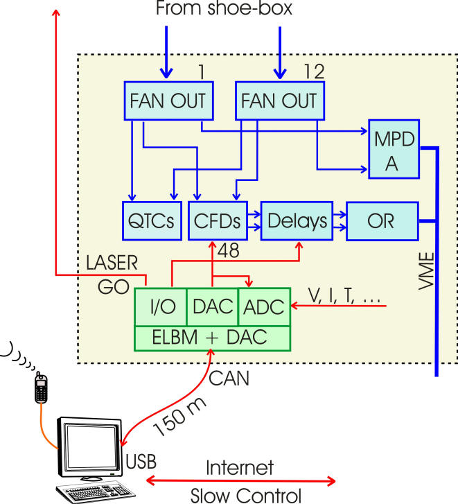
T0 and V0 detectors

 Fast Electronics (Slow Control System - Project)

 Radomir Kupczak

document.doc


       PVSS software (LabView?)


Block diagram of the ELMB ADC


Front side Board  ELMB3  


Back side Board  ELMB3


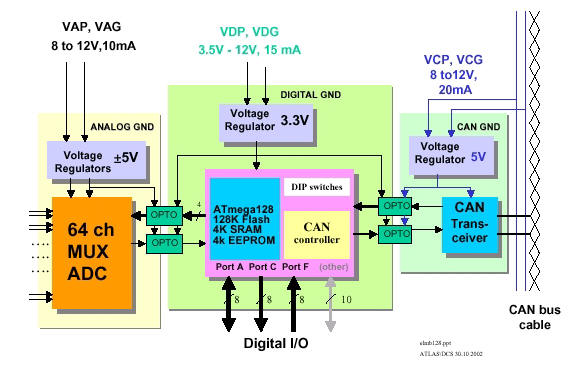
  Four differential 16 channel ADC inputs (64 chanels, range from -4.5V to 4.5V)

  One 8 bit bi-directional digital I/O (PORT A).
  One 8 bit digital output port (PORT C).
  One 8 bit input digital input port (PORT F).

  opto-isolated


Block diagram of the ELMB-DAC


Electronic ELMB-DAC


NIKHEF


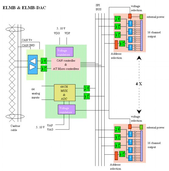
  4 x 16 channels 12-bit using four 12-bit (4-channel MAX525).

  Current output 0-20 mA, or 0-1 mA,(0 - 2,5 V)

  opto-isolated


Interface USB - CAN


ELMB CAN protocol


Links

Schematics of ELMB

Single board LMB

Schematics of ADC

Motherboard LMB

Motherbord front LMB

Motherboard back LMB

Connectors LMB

Programmer LMB

Description LMB DAC

Software LMB

CANopen sofware

Distribution

Appendix A

Appendix B